A simple Bluetooth adaptor for the E-Stim System 2B
The E-Stim systems Series 2B is a fairly compact electro box, and so ought to be a neat idea for things like play in clubs. But how d you control it without wires all over the place? One solution is to make a Bluetooth adaptor that plugs in to the digital link port (which is a serial connection). You can then control the 2B using my Android app via Bluetooth.
What's the point?
The main point of this, for me at least, is a bit of public play. Go to a club, with an electro plug in, the 2B and Bluetooth adaptor in my trouser or jacket pockets, and everything can be controlled by Boss, using the app on his phone - whether that's slowly cranking up the power, or a brief jolt from time to time if I've wandered off and he wants me back.
What do you need?
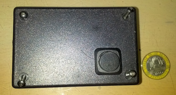
This is a pretty simple project; you need an off the shelf Bluetooth serial module, a battery holder, a couple of resistors, and some connectors. And a little box to put it in. This is my Bluetooth adaptor, next to a 10 Franc coin for scale (I know; I was the only one I could find at hand).

On the left hand side is a 3.5mm jack scoket into which a cable is plugged to link to the 2B. I did experiment with a smaller module that plugged directly into the 2B, with three jacks attached, plus pass-through sockets for the output, but it was a) hard to make it all align nicely without proper machining tools and b) in a small case, you can't fit in decent batteries to run the module.
Technical considerations
The HC-04 Bluetooth serial module has, I think, been replaced by a later generation, but the principle is the same. It's a small module that has a few connector pins for power, ground, Tx and Rx. The modules currently advertised on eBay say "5V" but that generally refers to the power supply level, not to the logic level. That's important because, though the 2B digital link is what's known as TTL, it's five volt TTL, whereas the Bluetooth module, while running from five volts, actually communicates at 3.3 volts. So plugging one directly into the other isn't recommended, and may fry the module.
However, there is a bit of latitude here; the "proper" solution is to use a dedicated chip to adapt the levels, but you can fudge it. There's not so much a difference between 3.3 and 5, and it turns out that when a 3.3V serial signal is set high (ie to the 3.3V level), that's good enough for a 5V receiver to realise what's meant. And 0 volts is 0 in any case. So, for sending data from the HC-04 to the 2B, you can simply connect the 3.3 volt output of the module (the TX link) to the input of the 2B.
In the other direction, though, you need to drop the voltage. The simplest way to do this is using a pair of resistors; in my unit I have a 2k2 and a 3k3 resistor, connected in series. The bottom of the 3k3 resistor is connected to the battery -v, which is also linked to the 'ground' or barrel of the serial connector, and the top of the 2k2 is connected to the input from the 2B. The RX pint of the HC-04 is connected to the junction between the two resistors. This drops the incoming voltage to around three volts, which again is close enough for the module to know when it's receiving a 1 or a 0.
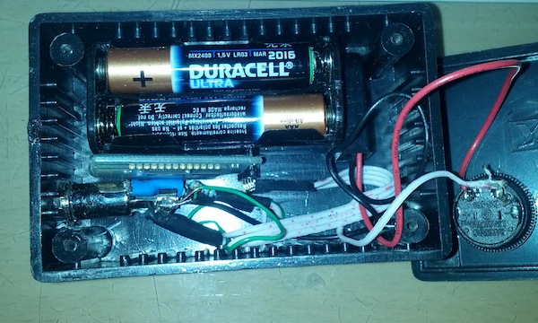
The diagram here shows the assembled module with the cover removed

Putting it together
So, putting this all together is pretty simpler. There are just a few connections to solder from the connector; a switch of some sort is handy, and if I were making another module, I'd use a slider with a little painted indicator so I know when it's on or off - the push button can be pressed a bit too easily in a pocket. I use four AAA batteries in a holder, which has a PP3-style connector, which just makes changing them easy; the supply rating of the HC-04 is actually between 3.6 and 6 volts, so this will do just fine.
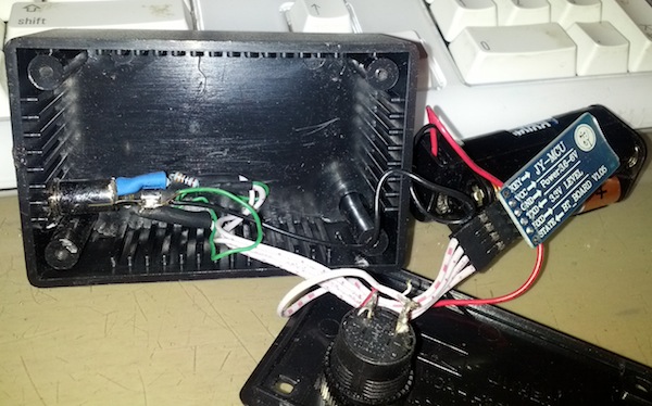
As you can see, you can do most of the connections on the back of the socket, with a bit of heat shrink sleeving to tidy everything up - no need to make a special circuit board, or anything like that.

The observant will have noticed I haven't yet included information here on which pin on the 3.5mm socket is TX and which is RX. That's the last bit of the puzzle, and the tip connector of the 3.5mm socket is TX data FROM the Bluetooth module, ie on the 2B side, the tip is RX (received data) - assuming, of course, that you link the adaptor to the 2B with a cable that's wired straight through and doesn't cross anything over.
How do you control it?
In my Android app, all you have to do is select the connection type as Bluetooth, and connect; the default pairing code is 0000. You can then control the 2B as if you were directly connected (though of course, if you go out of range, the connection is lost). You may also want to connect the module temporarily to your PC or Mac via the serial connection (swap round RX and TX, plug the E-Stim system link cable into the box) and set the Bluetooth module name using AT commands, so it has a name like 'Estim'.
Please note:
This is an experimental project; it works for me. But try it at your own risk - if you make a mistake, and damage the digital link port of your 2B, I can't accept any responsibility. Similarly if you wire it up wrong and break the Bluetooth module. Or burn yourself with a soldering iron. Or, indeed, do anything other than just read this page and look at the pictures. Not my fault, ok?
I should also stress that, while it's possible to link a Windows or Mac computer to the 2B using Bluetooth, if it has an adaptor, you really should get the official E-Stim systems cable. Not only does that give you the app you need to do firmware updates on your 2B, but I think you'd be lunatic to try doing a firmware update using a home-made Bluetooth adaptor powered from batteries. Plus, you can use the cable to program the Bluetooth module with the name you want, and alter other settings.